|
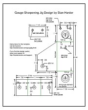
First download the template. The template is available in Acrobat PDF format.
Click Here to download template
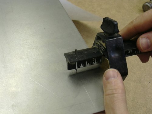
Print out the template and check to make sure it printed out at 100% scale by checking a few of the measurments with a ruler.
|
|
|
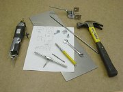
Tools and supplies needed to make the jig are shown here. The material I used is 16 gauge steel. A slightly thicker material would also work as long as it can be bent. Anything thinner that 16 gauge would not be strong enough to make a rigid jig.
I found 16 gauge steel sheets 6x13 inches at a local home center for less than $7.
- 6 inch wide sheet of 16 gauge steel. Two jigs fit nicely in a 6 x 4 3/4 sheet. A 6x13 sheet will make 5 jigs.
- 1 - 1/4 inch threaded rod, from 4 inches to 12 inches in length depending on grinder setup.
- 1 - 1/4 x 1 inch, 20tpi hex head bold, or shorter if available.
- 3 - 1/4 inch nuts.
- 1 - 8-32 x 1 1/4 inch thumb screw bolt
- 2 - 8-32 x 1/4 inch pan head bolts, any length up to an inch would be fine.
Tools needed:
- Bench vice or machinist vice
- Hammer
- hack saw, jig saw with metal blade or air body saw
- Drill press
- Drill bits: 1/4, 7/32, 9/64, and one the diameter of the shaft of the gouge.
- 8-32 tap. Options are discussed in the instructions on how to build the jig without a tap.
- Center punch
- 9/16 wrench, or adjustable wrench
- Screw driver
- Masking tape
- Files, rat tail and flat.
- Awl or marking gage
|
|
|
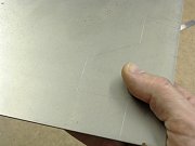
Tape the paper template to a sheet of 16 gauge steel and using a center punch, mark each hole and the corners with a strike of a hammer to the punch.
The two large holes are to be the shaft diameter of the gouge which this jig is being made for.
The template is marked for either 3/8, 1/2 or 5/8 diameter shafts.
For other diameter gouges, the hole location would need to be adjusted so the edge of the hole is about 1/4 inch from the bend line.
|
|
|
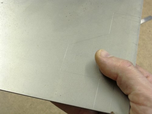
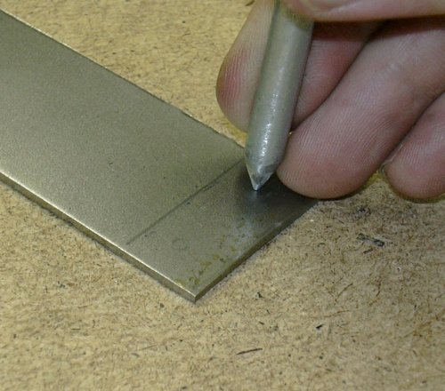
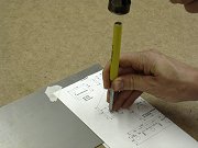
Connect the cut lines around the jig with an awl or use a marking tool as shown here.
|
|
|
Actually, a pencil mark is easier to see than a scribe line.
The bend lines are marked also, but care is taken not to cut on those lines.
|
|
|
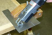
A hack saw with a fine toothed blade would cut this soft thin steel.
A jig saw or even a band saw would also work if it had the right blade.
However, I like my air body saw so that's what I used.
|
|
|
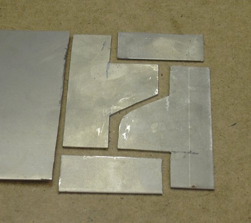
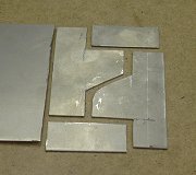
The template is such that it lays out very efficiently on 6 inch wide material. Here are two jigs cut out except for the small flute alignment part that is small enough to cut out of any small scrap piece of steel.
|
|
|
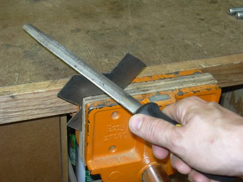
After cutting there is a really sharp burr around the part. Here I'm rounding all the edges with a file so I don't cut myself later.
|

|
|
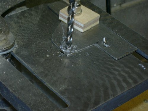
Drill the holes as marked on the template.
The large two holes are to be the diameter of the gouge the jig is being made for.
Starting with a small bit and redrilling with increasing sized bits will result in a rounder hole.
The metal must be clamped well in place for safety.
|

|
|
The holes need to be cleaned up with a flat file. Here I'm enlarging the hole just a little so that the gouge slides freely through it.
|

|
|
There, it fits good now. It slides and rotates smoothly.
|
|
|
I used a 8-32 tap to thread the three small holes. If a tap is not available, there are other options. The two bolts holding on the small flute alignment piece could just as easily be drilled larger and nuts used to fasten it together.
For the tightening screw, a nut could be soldered or brazed in place on top of the steel. But taps are much easier.
|
|
|
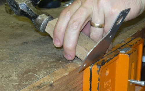
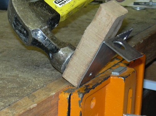
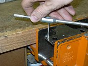
I'm showing the bending operations using a bench vise that most woodworkers would have available to them. A machinist vice would work a little better.
I clamp the piece in the vice so that the bend line is just visible above the jaws of the vise. Then using a scrap of wood and a hammer, strike the steel so that it bends around the jaw of the vise.
Bend to 90 degrees.
|

|
|
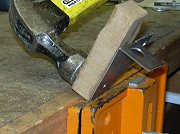
Here I'm bending the other end. Exactness is not necessary, though it will look better if it's uniform in shape.
|
|
|
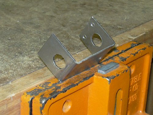
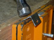
Now I'm folding down the part of the bracket that will attach to the leg of the jig. Again, bend to 90 degrees.
|

|
|
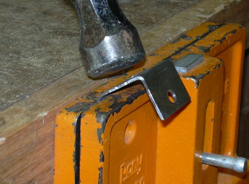
The leg bracket gets bent the same way.
|
|
|
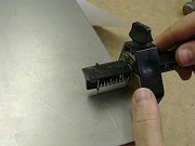
Now, the jig has a flute alignment piece to orient the gouge so that it does not rotate in the jig. Holding the gouge in the jig with the flute horizontal to the base of the jig, set the
alignment piece in position and mark the hole locations with a pencil. Also, mark the alignment piece along the top of the jig so the alignment piece can be cut to size.
Note that the alignment surface that touches the top of the flute must be perpendicular to the direction of the leg of the jig in order to grind a symetric bevel.
|

|
|
With a center punch, mark the two holes and drill 7/32. Then cut the piece to length. Drilling before cutting makes it easier to clamp the piece in the drill press.
|

|
|
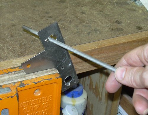
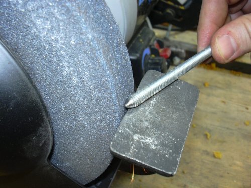
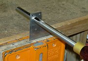
The leg is made of a 1/4 inch threaded rod with the end ground to a dull point. This end is the pivot point that sets in the positioning jig which is attached to the grinder base.
The length of this rod depends on the gouge grind shape desired.
It can be adjusted a little in the jig but should be made approximately the right length for the desired grind for that particular gouge.
|

|
|
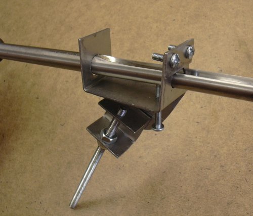
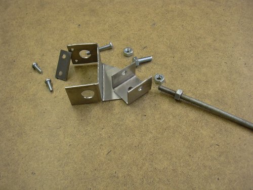
Now we have all the parts fabricated. All that's needed is a wrench and screw driver to put it all together.
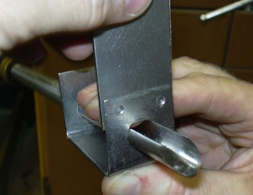
Insert the gouge before tightening the flute alignment piece. Adjust the alignment of the gouge so that the flute of the gouge is perpendicular to the line from the center of the gouge to the end of the leg.
The holes in the alignment piece are oversized so it can be adjusted to make the gouge fit snugly in place.
|
|
|
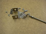
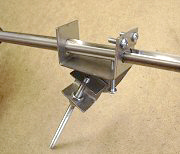
The completed project. The bolts could have been cut off to make it look neater.
This photo shows a pan head bolt for the tightening screw.
I found that this didn't tighten the gouge in place well enough so I have replaced it with a thumb screw or eye bolt.
|
|
|
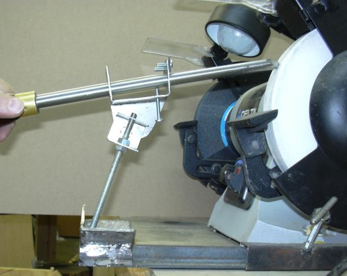
The jig in use. The screw through the bottom of the jig is just thumb tightened to hold the gouge into the jig. This jig is not as sturdy as commercially available versions but sharpening is a delicate operation that should be done without force. Pressing hard on the grinder will just overheat the steel.
|

|